0 To 25Gb Ethernet: Part 2 The Scrambler
Make sure to read the previous post for an overview of what we will be talking about today:
- 0 To 25Gb Ethernet: Part 0
- 0 To 25Gb Ethernet: Part 1 The PMA
- 0 To 25Gb Ethernet: Part 2 The Scrambler (this post)
- 0 To 25Gb Ethernet: Part 3 The Encoder
What is the PCS and the Scrambler
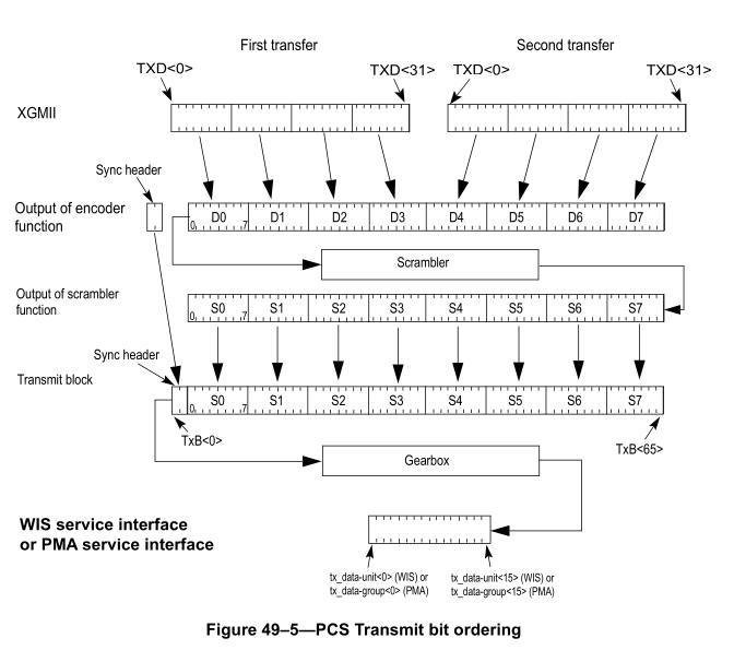
The PCS (Physical Coding Sublayer) interfaces between the XGMII interface and the PMA interface. XGMII transmits 8 data bits and one control bit per byte lane. This then goes into the Encoder to convert the (64+8) bits into (64+2) bits per block. These 64 encoded bits are then passed into the Scrambler which outputs a different set of 64 nits to be transmitted over the wire. The two first bits in the block are a sync header and are transmitted directly.
These components and the bit ordering can be seen in Figure 49-5
In this blog post we are going to be working on designing the Scrambler.
How does the Scrambler work
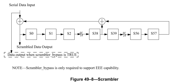
The scrambler is a LFSR (Linear Feedback Shift Register) that ensures there aren’t long stretches of 1s or 0s. The specification of the Scrambler is given as a diagram of the LFSR seen below
Starting simple
The simplest approach to implementing this LFSR is simply implementing a LFSR. This is very clearly not a performant method for implementing the Scrambler because it will take 64 clock cycles to process the 64 bits (we can only input one bit per cycle) which will take far too long. We ideally want to process all 64 bits at once in a single clock cycle. For now though we will implement the simplest “functional” scrambler to get a better idea of how it works.
module scrambler #(
    parameter bit [57:0] INITIAL_STATE = 58'hFFFFFFFFFFFFFFF
) (
    input  wire  i_clk,
    input  wire  i_arst,

    input  wire  bit_in,
    output logic bit_out
);

    logic [57:0] lfsr_state;

    wire state_xor;

    xor state (state_xor, lfsr_state[38], lfsr_state[57]);
    xor in_xor (bit_out, bit_in, state_xor);

    always_ff @( posedge i_clk or posedge i_arst )
    if (i_arst)
        lfsr_state <= INITIAL_STATE;
    else
        lfsr_state <= {lfsr_state[56:0], bit_out};
endmodule
from this we can start to see the scrambler works.
Modelling the Parallel Scrambler
For efficiency we want to take all 64 bits of a block and scramble them in parallel. We can start to do this by modelling a toy scrambler that only has three state registers and works on blocks of 4 bits.
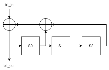
This scrambler is a little easier to reason about, so lets start with the starting state in variables
\[ S_i = \begin{bmatrix} s_{0,i} & s_{1,i} & s_{2,i} \end{bmatrix} \]
I have given the state vector a subscript \(i\) to hint that this state vector will change over time and we will see how that state change happens. Before we do that we need to create some notation for the xor operation and the and operation (this will because useful soon). If we notice that each of our variables can only hold the values 0 and 1 we can see that and is the same thing as standard multiplication. Through a little creativity we also notice that xor is modulo 2 addition. With these two operations we need mapped to addition and multiplication we can create a matrix that when multiplied by the state augmented with the input advances the system one time step.
\[\left[\begin{array}{cccc|ccc} d_3 & d_2 & d_1 & d_0 & s_0 & s_1 & s_2 \end{array}\right] \left[\begin{array}{cccc|ccc} 0 & 1 & 0 & 0 & 0 & 0 & 0\\ 0 & 0 & 1 & 0 & 0 & 0 & 0\\ 0 & 0 & 0 & 1 & 0 & 0 & 0\\ 0 & 0 & 0 & 0 & 1 & 0 & 0\\ \hline 0 & 0 & 0 & 0 & 1 & 1 & 0\\ 0 & 0 & 0 & 0 & 0 & 0 & 1\\ 0 & 0 & 0 & 0 & 1 & 0 & 0\\ \end{array}\right]\]If we inspect this matrix we can see that it has some interesting properties that correspond to the properties of the shift register, namely the first diagonal above the major diagonal is all ones. This will shift all the elements of the vector one element to the left. secondly we can see that the only column that doesn’t match this pattern is the 5th column which has ones in all the rows of the elements that are xored together.
Multiplying this out we get
\[\left[\begin{array}{cccc|ccc} 0 & d_3 & d_2 & d_1 & d_0 + s_0 + s_2 & s_0 & s_1 \end{array}\right]\]We can visually verify that the right three elements are correctly the state in the shift register after the first element is shifted in, in terms of the initial state.
We can also see that the element in the fourth column is equal to the output for the 0th index
In order to simplify this calculation we can write a script to generate this matrix and multiply it out.
import numpy as np

inputs = 4
states = 3

poly = 0b1011

assert poly >> states == 1, "Polynomial must be states + 1 bits and have top bit set"

mat = np.diag([1] * (inputs + states - 1), 1)

mat[:, inputs] = mat[:, 0] = [
    1 if (poly << (inputs - 1) >> i) & 1 else 0 for i in range(inputs + states)
]

mat = np.linalg.matrix_power(mat, inputs) % 2

print(mat)

print(
    f"""module scrambler_gen(
    input wire [{inputs + states - 1}:0] data_in,
    output wire [{inputs + states - 1}:0] data_out
);"""
)

for i in range(inputs + states):
    print(
        f"assign data_out[{i}] = "
        + " ^ ".join([f"data_in[{j}]" for j in range(inputs + states) if mat[j, i]])
        + ";
    )
print("endmodule")
The only difference in this code is we also add the output into the first columns of the vector so we can generate a single matrix at the end.
\[\left[\begin{array}{cccc|ccc} 0 & 1 & 0 & 0 & 0 & 0 & 0\\ 0 & 0 & 1 & 0 & 0 & 0 & 0\\ 0 & 0 & 0 & 1 & 0 & 0 & 0\\ 1 & 0 & 0 & 0 & 1 & 0 & 0\\ \hline 1 & 0 & 0 & 0 & 1 & 1 & 0\\ 0 & 0 & 0 & 0 & 0 & 0 & 1\\ 1 & 0 & 0 & 0 & 1 & 0 & 0\\ \end{array}\right]\]The output of this code is
[[1 0 0 0 1 0 0]
 [1 1 0 0 1 1 0]
 [1 1 1 0 1 1 1]
 [0 1 1 1 0 1 1]
 [1 0 1 1 1 0 1]
 [1 1 1 0 1 1 1]
 [0 1 1 1 0 1 1]]
module scrambler_gen(
    input wire [6:0] data_in,
    output wire [6:0] data_out
);
assign data_out[0] = data_in[0] ^ data_in[1] ^ data_in[2] ^ data_in[4] ^ data_in[5];
assign data_out[1] = data_in[1] ^ data_in[2] ^ data_in[3] ^ data_in[5] ^ data_in[6];
assign data_out[2] = data_in[2] ^ data_in[3] ^ data_in[4] ^ data_in[5] ^ data_in[6];
assign data_out[3] = data_in[3] ^ data_in[4] ^ data_in[6];
assign data_out[4] = data_in[0] ^ data_in[1] ^ data_in[2] ^ data_in[4] ^ data_in[5];
assign data_out[5] = data_in[1] ^ data_in[2] ^ data_in[3] ^ data_in[5] ^ data_in[6];
assign data_out[6] = data_in[2] ^ data_in[3] ^ data_in[4] ^ data_in[5] ^ data_in[6];
endmodule
When interfacing with the scrambler we must remember that the bit ordering is backwards for the data sections but this can be handled in a wrapper module like so
module scrambler_parallel (
    input wire [3:0] data_in,
    input wire [2:0] state_in,

    output wire [3:0] data_out,
    output wire [2:0] state_out
);

    wire [6:0] scrambler_out;
    scrambler_gen scrambler_inst (
        .data_in({state_in, { << {data_in}}}),
        .data_out(scrambler_out)
    );

    assign data_out = { << {scrambler_out[3:0]}};
    assign state_out = scrambler_out[6:4];
endmodule
Descrambler
The associated descrambler can be described as follows
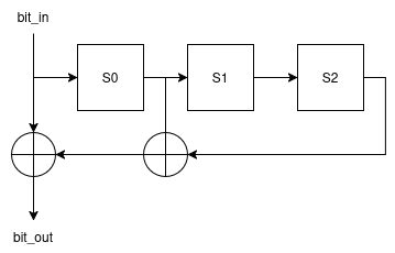
We can also see that the associated matrix for the descrambler only has the polynomial in the first column and not in the first state column
\[\left[\begin{array}{cccc|ccc} 0 & 1 & 0 & 0 & 0 & 0 & 0\\ 0 & 0 & 1 & 0 & 0 & 0 & 0\\ 0 & 0 & 0 & 1 & 0 & 0 & 0\\ 1 & 0 & 0 & 0 & 1 & 0 & 0\\ \hline 1 & 0 & 0 & 0 & 0 & 1 & 0\\ 0 & 0 & 0 & 0 & 0 & 0 & 1\\ 1 & 0 & 0 & 0 & 0 & 0 & 0\\ \end{array}\right]\]Editing the code to generate this matrix we get
[[1 0 0 0 1 0 0]
 [1 1 0 0 0 1 0]
 [0 1 1 0 0 0 1]
 [1 0 1 1 0 0 0]
 [0 1 0 1 0 0 0]
 [0 0 1 0 0 0 0]
 [0 0 0 1 0 0 0]]
module scrambler_gen(
    input wire [6:0] data_in,
    output wire [6:0] data_out
);
assign data_out[0] = data_in[0] ^ data_in[1] ^ data_in[3];
assign data_out[1] = data_in[1] ^ data_in[2] ^ data_in[4];
assign data_out[2] = data_in[2] ^ data_in[3] ^ data_in[5];
assign data_out[3] = data_in[3] ^ data_in[4] ^ data_in[6];
assign data_out[4] = data_in[0];
assign data_out[5] = data_in[1];
assign data_out[6] = data_in[2];
endmodule
Testing the Scrambler and Descrambler
Now we can loop the scrambler output into the descrambler input and ensure the scrambler input equals the descrambler output. Since this is a self-synchronizing scrambler we do not need to initialize the two sides with the same initial state. If the sides are not initialized the same the first block sent will not be decoded correctly but the second and later blocks will be decoded properly. An example loopback module is below
module scrambler_loop #(
    parameter bit [57:0] INITIAL_STATE = 58'hFFFFFFFFFFFFFFF
) (
    input wire i_clk,

    input wire [63:0] data_in,

    output wire [63:0] data_out
);

    reg [57:0] scrambler_state = INITIAL_STATE;
    wire [57:0] scrambler_state_out;

    reg [57:0] descrambler_state = INITIAL_STATE;
    wire [57:0] descrambler_state_out;

    always_ff @(posedge i_clk) begin
        scrambler_state <= scrambler_state_out;
        descrambler_state <= descrambler_state_out;
    end

    wire [63:0] scrambled;

    scrambler_parallel scrambler_inst (
        .data_in(data_in),
        .state_in(scrambler_state),

        .data_out(scrambled),
        .state_out(scrambler_state_out)
    );


    descrambler_parallel descrambler_inst (
        .data_in(scrambled),
        .state_in(descrambler_state),

        .data_out(data_out),
        .state_out(descrambler_state_out)
    );

endmodule
The above loopback expects 64 bit blocks like the ethernet scrambler. The full ethernet scrambler/descrambler pair can be generated with by setting inputs=64 states=58 and poly=0x400008000000001
Next Steps
As you might have noticed from the first diagram in this post we switched up the order a bit and jumped over the gearbox when moving up the sublayer stack. This is because the PMA described in the previous post has the gearbox integrated into it so we dont need to develop our own. Even though we don’t need our own gearbox we will still be making one in the next post.