0 To 25Gb Ethernet: Part 3 The Encoder
Make sure to read the previous post for an overview of what we will be talking about today:
- 0 To 25Gb Ethernet: Part 0
- 0 To 25Gb Ethernet: Part 1 The PMA
- 0 To 25Gb Ethernet: Part 2 The Scrambler
- 0 To 25Gb Ethernet: Part 3 The Encoder (this post)
Last post I promised this post would be about the synchronous gearbox, which from the title we can see this one isn’t. The gearbox is coming but it is going to be delayed till we start covering low latency techniques.
Today, we will be covering the last part of the PCS: The Encoder
The Encoder
As we saw in the last post about the scrambler, we need to scrambler 64 bits and then attach the 2 header bits. This is a total of 66 bits, but the XGMII interface transfers 64+8=72 bits per cycle. The way Ethernet makes up this discrepancy is the encoder.
Block Formats
XGMII transfers 8 bytes lanes per block and each of these lanes can either hold a data byte or a control byte as indicated by the control bit lane. The following table shows how to convert from XGMII to a 64B/66B block.
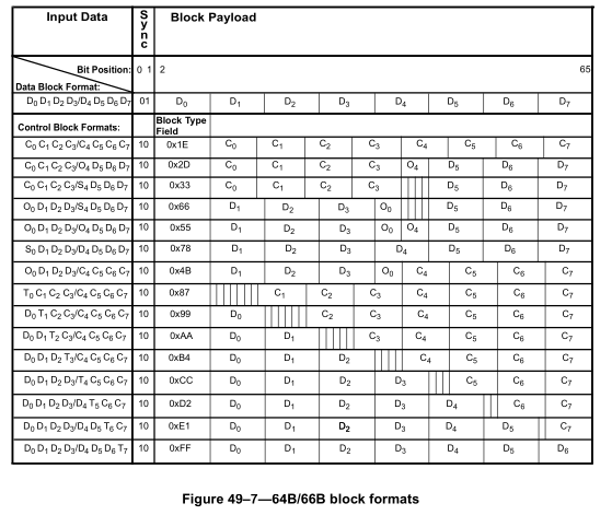
As we can see there are only two options for the sync header.
- 2’b10 for 8 data bytes
- 2’b01 for mixed data and control
(I will always write all binary and hexadecimal numbers with MSB in the leftmost position and LSB in the rightmost)
All other sync headers are invalid and will be used by the block lock state machine to properly align blocks.
Data Block
Data blocks are very easy as all of the byte lanes are just passed through as the block payload.
Control Blocks
Control blocks are a little more complicated as they have a type field. The lowest 8 bits of the block payload determine the format of the rest of the payload.
- 8’h1E Indicates idle control blocks with all upper bits 0
- 8’h2D Indicates ordered set and will not be implemented
- 8’h33 Indicates start of frame in lane 4
- 8’h66 Indicates ordered set and start of frame in lane 4
- 8’h55 Indicates ordered set and will not be implemented
- 8’h78 Indicates start of frame in lane 0
- 8’h4b Indicates ordered set and will not be implemented
- 8’h87, 8’h99, 8’hAA, 8’hB4, 8’hCC, 8’hD2, 8’hE1, 8’hFF Indicates termination of frame in lanes 1-8 respectively
So in total we need to implement 12 different block types without ordered set blocks.
This is pretty easy to do with a case statement completely combinationally.
Finishing the PHY
The last thing we need to make the PHY functional is the block lock state machine which aligns the blocks on the receiver with the transmitter. The block lock state machine is detailed in the figure below:
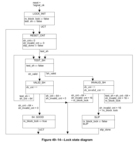
Once we implement this state machine we can transmit idle blocks we should be able to use a loopback cable and receive the same idle blocks after achieving block lock. This should also allow us to connect to a NIC to the FPGA and it should bring up the link and send idles down the wire.
Next Steps
This is a much shorter blog post than the past few as the encoder is the simplest part of the PCS to understand. The next higher layer is the MAC which handles constructing Layer 1 frames and handles padding and gaps.